By Rich
Among the rules of installing water, fuel, or waste tanks on a boat is the Golden Rule: marine tanks must be installed in such a manner that no significant forces act upon the tanks’ fittings. Let me say that again, in case it wasn’t entirely clear:
Marine tanks must be installed in such a manner that no significant forces act upon the tanks’ fittings.
We’re not sure if Sabre can be credited with this fail or someone who worked on the boat subsequently, but our Sabre 42’s aft holding tank was installed in a manner that pretty much guaranteed that the tank would crack at the fittings and begin to leak. Why? There were two major installation problems:
- The tank was unsupported longitudinally in the boat. That is to say that while the tank could not move athwartship (side to side) it could slide fore-and-aft in such a manner that the fittings on both ends of the tank could contact the bulkheads of the compartment in which it lives.
- The clearance between the tank fittings and those same bulkheads was insufficient, virtually guaranteeing that when (not if) the tank moved, the fittings would contact those bulkheads with the force of that contact being directly proportional to the weight of the tank. The more full the tank (ewwwww) the more force would be exerted.
As result of #1 above combining with #2 above, our tank cracked and began to leak at all three of its fittings when our boat was under prior ownership. In a terribly misguided attempt to fix the problem, the prior owner removed the waste hoses and replaced them with PVC pipes. Apparently be believed that old hoses were the source of bad smells coming from the sail locker, not a leaking tank. The use of PVC for marine plumbing is a very poor practice for two reasons. First, should the boat be improperly winterized, freezing water is much more likely to crack PVC than rubber hoses, which can stretch to a greater degree before cracking. Second, I refer our dear readers back to the Golden Rule of marine tank installation above:
Marine tanks must be installed in such a manner that no significant forces act upon the tanks’ fittings.
When solid piping is installed in a marine environment, the odds of forces being applied to the tank’s fittings shoot way up because boats flex and / or the tanks move around. Hoses flex easily, while solid plastic piping does not. The installation of a length of flexible hose between any such solid piping and tank fittings can mitigate these risks, but the hose must be of a sufficient length to prevent any significant forces from being applied to the fittings. These lengths of flexible hose are called “couplers.” Our poor, misguided prior owner either significantly overestimated his own mechanical abilities or hired a very crappy vendor to do the work because his PVC retrofit in some places used couplers that were far too short to have any effect but in most critical locations omitted them altogether.
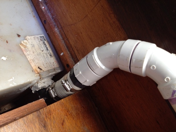
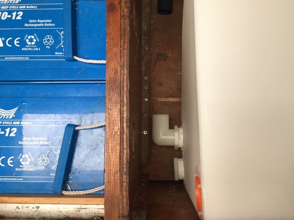
The results of combining the original bad tank installation with the even worse repair attempt were more and faster leaks which our poor fellow then tried to fix by spreading caulk (seen in the photo above) on the outside of the tank – an idiotic measure that had no effect.
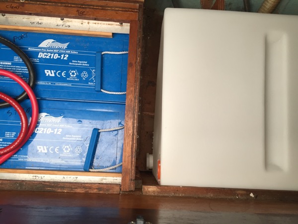
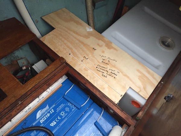
Fitting our new tank in this weekend, the issues of insufficient clearance and a lack of longitudinal support were immediately clear. In the photo below, a test fit showed that with the fittings installed the new tank would have exactly zero clearance between the fittings and the bulkhead.
After some time noodling on the issue, I decided to cut a small hole out of the (non structural) bulkhead aft of the tank to allow the vent fitting to poke through.
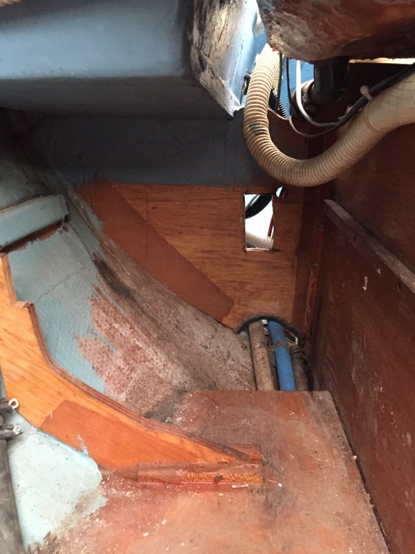
That change provided sufficient clearance for the fittings on the forward edge of the tank, but I still needed some means of preventing the tank from sliding around while the boat was underway.
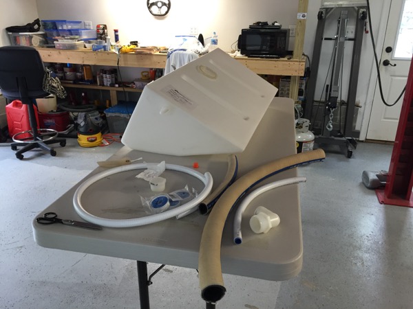
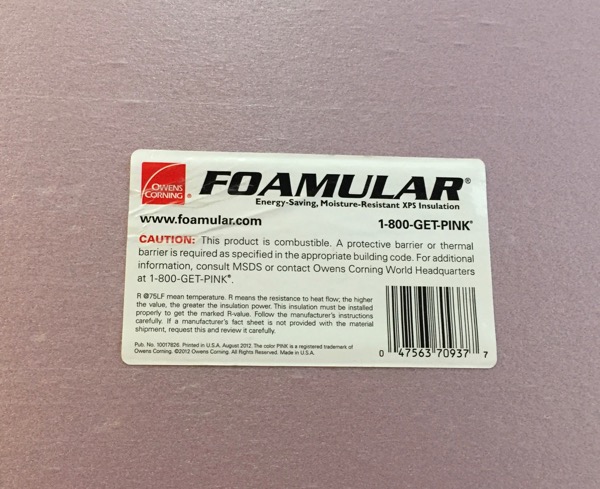
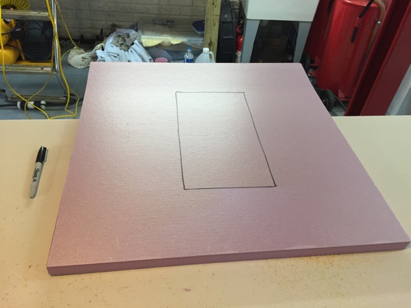
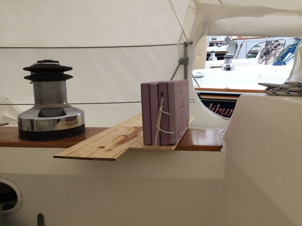
Calling it a day, I considered this problem overnight and struck upon the following solution (with Brian’s help!): I could suspend blocks of light material from above that would fill the gap between the bulkhead and the tank without resting on the hoses and fitting below. At Home Depot I found all of the materials I needed: some very thin plywood and Owens Corning “Foamular” foam insulation. The foam insulation is light yet very strong in compression – exactly what I needed.

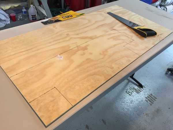
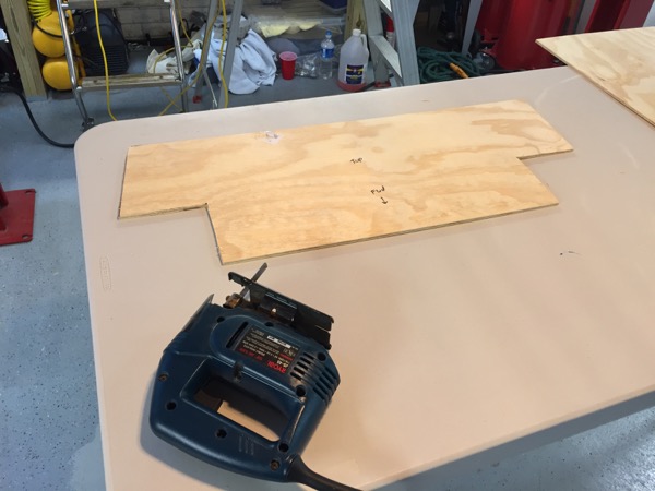
I cut the plywood to a width exactly equal to the space above the tank, and with a depth sufficient that it would easily support the light insulation. A section of the plywood was designed to be suspended over the gap between the tank and the bulkhead.
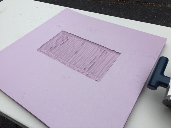
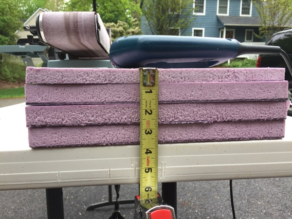
Next I cut the foam insulation into four blocks of the dimension I needed, but that resulted in 1/2″ greater thickness than necessary (4″ instead of the 3.5″ that needed to be filled). Cutting one of the blocks into half thickness with a saw proved to be impossible (at least with respect to accuracy) so I struck upon the following idea. I selected a fresh sheet and used a router to grind out a hollow of roughly the dimensions the fourth block would need to be. My router bit was tapered, which left something of a “tread” pattern in the block.
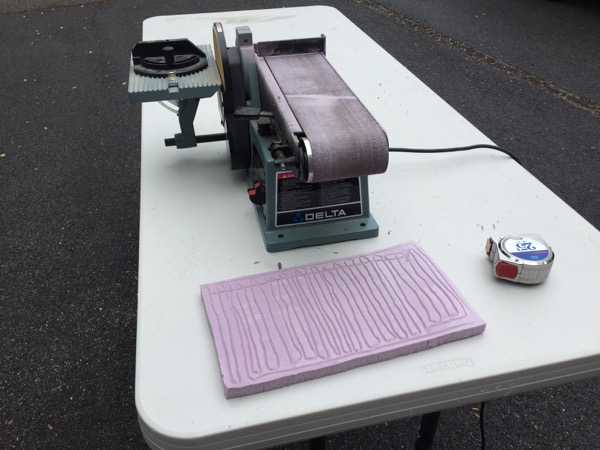
The “tread” pattern proved to be super useful, as the “treads'” maximum depth were about the half inch deep I was looking for. I cut the new block out and then used a belt sander to thin it more closely to the 1/2″ I was looking for. The major benefit of the “treads” was that I could fit the foam into the boat and gradually sand down the thickness of the block to exactly what I needed, using the “treads” as a visual guide to assure that my sanding was being done evenly across the block. Perfect!
After a few test fits I had the ideal thickness , so I laminated all of the blocks together with epoxy to form a single block of the ideal dimensions.

From there it was only a process of tying the foam block to the plywood so that it would be suspended in the gap without dropping down onto the hoses below. A couple of small holes would keep the string captive. Given the weight of the foam, loads on the string will be trivial.
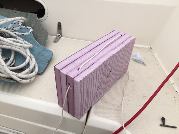
And finally the complete assembly could be lowered into place.
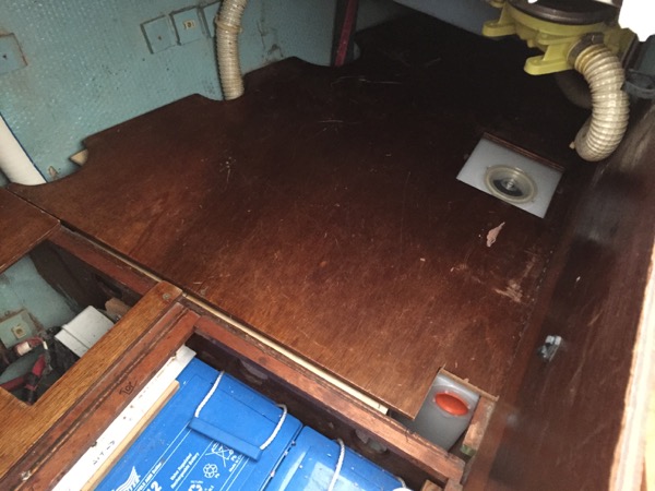
A test fit of the sail locker floor above showed everything fit perfectly. The plywood lives happily in a small gap between the top of the tank and the floor above it.
I’m waiting on one final part to arrive to complete plumbing of the tank, but once it comes in this project will be buttoned up.

This is a perfect example of taking time and thinking logically! (Careful! The open nature of this blog could cause you to get and offer from Nautor or Baltic yachts!
Interesting post. I can’t believe Sabre would have done this on the original boat. Have you looked at similar Sabres to see how it was originally done?
I haven’t – mainly because this tank lives below the “floor” of the sail locker, so it’s not a place one views very often. I agree though – it’s as likely as not that someone removed bracing that Sabre originally had in there – especially given the awful standard of work that has characterized much of the work that was done on this boat by prior owners and / or boat yards post-Sabre.